
Table of Contents (click to expand)
Diffraction is the bending of waves around an obstacle. A diffraction grating is an obstacle with many slits that diffracts waves in a particular pattern.
Diffraction, along with interference and polarization, is an indisputable proof of the wave nature of light. It is diffraction that makes the light radiated by a source detectable, even when its path is obstructed by an obstacle. The light, like water, flows around the obstacle to reach our eyes. Diffraction is why we can detect a source that is situated beyond the curve or why the edges of a cloud obscuring the Sun still gleam, accentuating what we call its silver lining.

However, does the stream of light always flow around the obstacle? No, particularly when the obstacle is too large. A detailed understanding of the phenomenon of diffraction will reveal why this is the case.
Huygens’ Principle
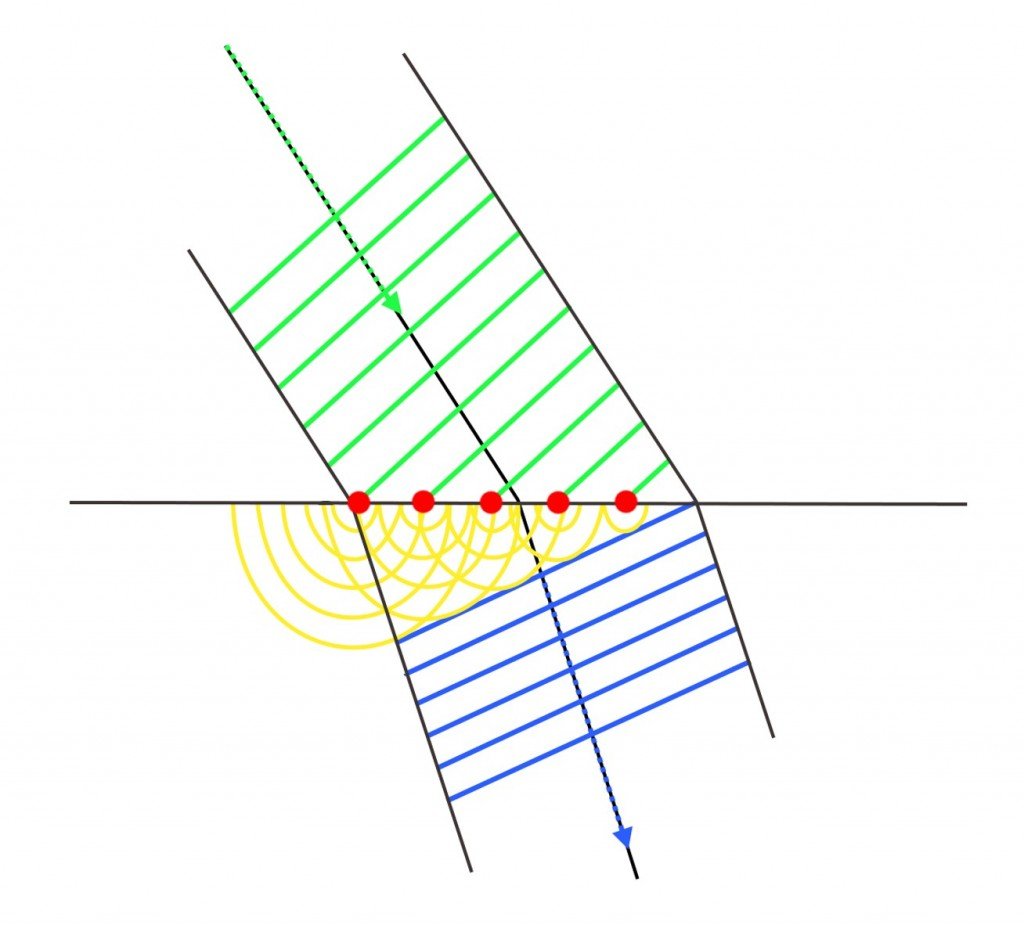
Contrary to Newton’s belief, Christiaan Huygens, in the 17th century, suggested that light doesn’t behave like a particle, but rather like a wave. He postulated what is now called Huygens’ principle: every point on a wave of light is a source of secondary waves that travel at the same speed as light. He also elegantly explained the occurrence of optical phenomena, such as reflection and refraction, with his wave theory of light. However, Huygens could never demonstrate the wave nature of light. He failed to prove his claims experimentally.
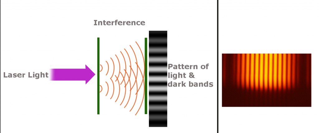
A century later, it was the British polymath Thomas Young who successfully demonstrated how light behaves like ripples in a pond by forcing light to squeeze through two adjacent slits. What the squeezed lights illuminated on a screen ahead of them is now called an interference pattern – a uniform, alternating pattern of bright and dark bands.
The discovery vindicated Huygens, as light cannot bend or flow around an obstacle unless it obeys his principle. Only waves interfering with each other can form such a pattern. Young immediately realized that when the two waves are squeezed between the slits, a bright band is produced when the peak of one ripple interferes constructively with or is added to the peak of another ripple, while a dark band is produced when the peak of a ripple interferes destructively with or negates another ripple. The addition causes the luminosity of the region to double, whereas the negation renders the region utterly dark.
What’s wonderful is that the pattern can be generated with a single slit as well. However, in a pattern generated by a single slit, unlike the pattern generated by two slits, the intensity of light is not evenly distributed. The pattern is called a diffraction pattern, because the light with which it is painted is diffracted.
However, before we can understand how the slit diffracts the light, let’s make one thing clear. While light does experience interference, it is only conspicuous when the two sources of light are both monochromatic — emitting light of a single wavelength — and coherent — emitting identical waves of a constant phase difference. When the sources are incoherent or multi-chromatic — or worse, both (which is the case with white light) — the bands produced are indistinguishably muddled and not as uniform and distinct. These conditions also must be fulfilled to conspicuously demonstrate diffraction.
Also Read: What Is Light? Matter Or Energy?
The Single Slit Experiment
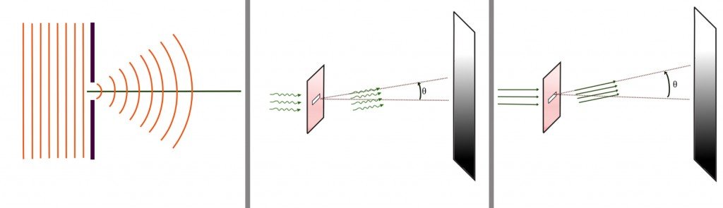
While the two conditions must be fulfilled to ensure that the phenomenon is observable, there exists another condition which, if not fulfilled, prevents the phenomenon from occurring in the first place. A diffraction pattern is produced only if the wavelength of light λ is comparable to or larger than the size of the obstacle around which it will flow. If the width d of the slit is very large — similar to how a needle would fall in a slot for coins — the light would simply pass untouched, and a single bright spot would be illuminated on the screen ahead. However, when the slit is narrow, the light is diffracted spectacularly.
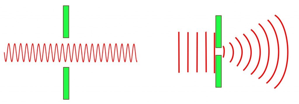
As already explained, when the waves of light encounter the slit, they bend and squeeze through, like running water suddenly spouting out from a crack in the pipe. As the waves bend and change direction, they appear to spread and mimic ripples. The ripples can be approximated with parallel lines. Why? Because the screen is so far away that the waves appear to be straight lines, just how currents in the Nile would be imperceptible from the International Space Station.
Now, according to Huygens’ principle, every point between the edges is a source of waves. While the interference pattern studied above is formed due to the interference of two different waves emanating from two different slits, a diffraction pattern is formed due to the interference of different waves emanating from a single source. How is this possible?
The secondary waves that emanate from these point sources interfere with each other as they bend around the slit. This is because the bending causes a wave to travel a longer distance than another wave. Let’s assume that the parallel rays bend at the slit at an angle α.
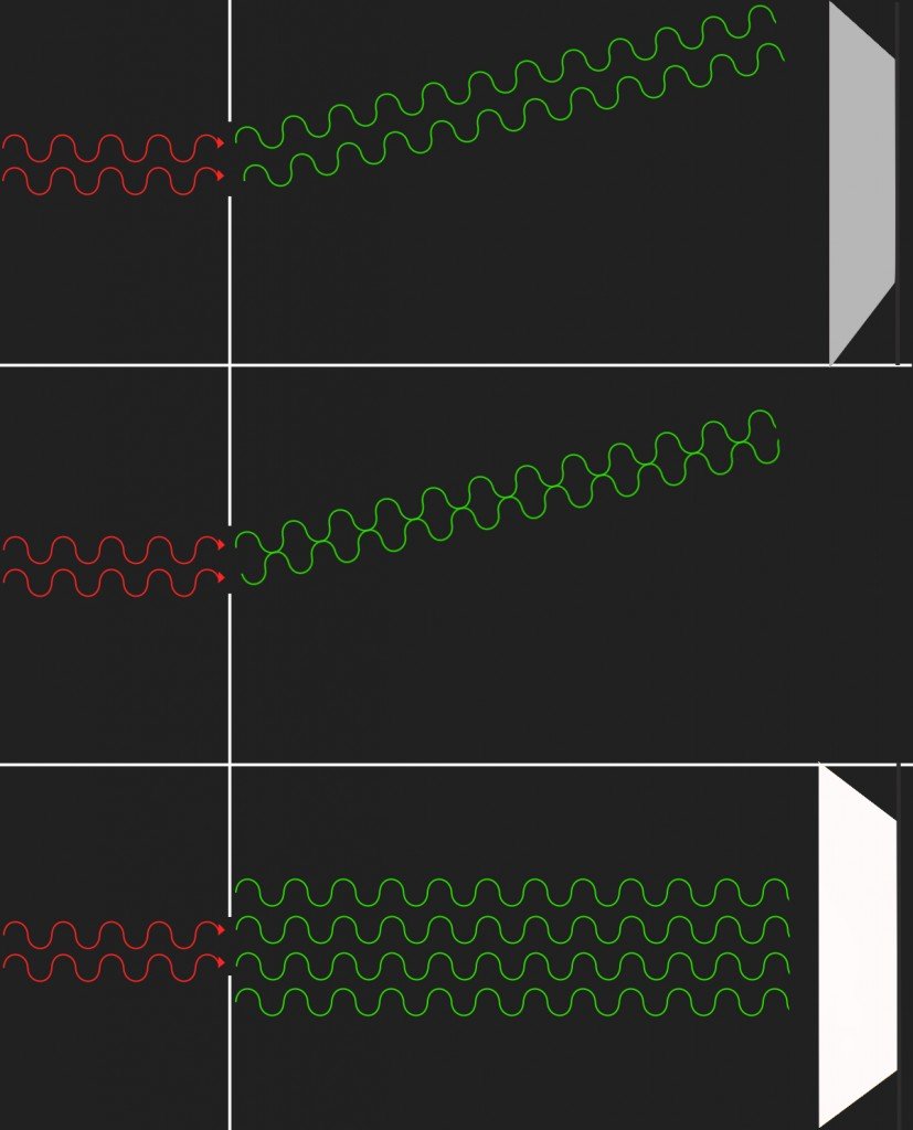
Now, there exists a value of α at which when two waves bend, they are rendered out of phase. These two waves negate each other or interfere destructively to produce a minimum – a region of darkness. Here, the peak of one wave is superimposed on the valley of the other.
There also exists a value of α at which, when two waves bend, they are rendered in phase with each other. These two waves add or interfere constructively to produce a maximum – a region of brightness. Here, the peak of one wave is superimposed on the peak of another. It is now obvious why the pattern is merely a bold bright spot when the slit is wider than the light’s wavelength. When the light simply falls through the wide slit, not a single wave bends. They all pass undeflected and therefore exist in the same phase. They all interfere constructively on the screen ahead.
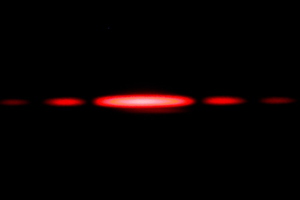
The diffraction pattern is an alternate pattern of maximums and minimums that looks like this:
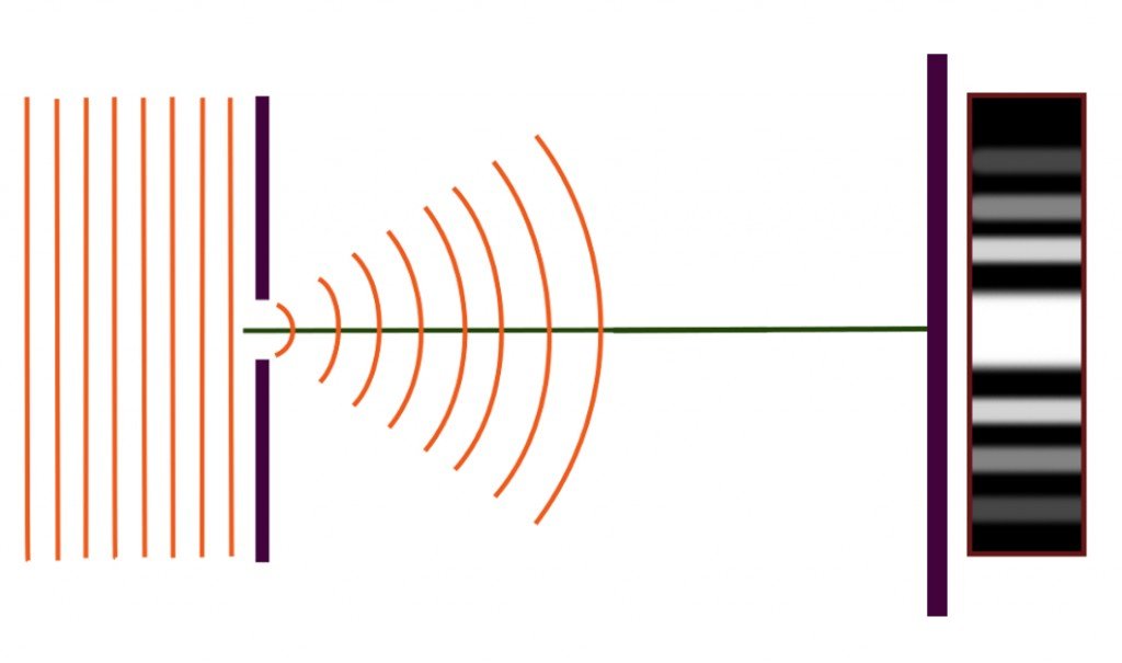
The spot in the center of the axis, spanning equal lengths on both sides, is the brightest. This is the central maximum. It is flanked on both sides by the first-order minimums, which are followed by the first-order maximums, which are followed by the second-order minimums and so on, alternatively. Even though the disparity is imperceptible to the human eye, the intensity of maximums decreases as we move farther from the central maximum. What determines the distance by which the maximums or minimums are separated? And what determines the pattern’s intensity? Let’s find out.
Also Read: What Is The Double-Slit Experiment?
The Distance Of Separation
Let’s redraw the diagram, illustrating the deflection of waves above. To reach the center of the axis ahead, waves generated by points equidistant from the center of the slit — say, the first and the last point — must travel an equal distance, that is, such a pair of waves is in phase. This is why the central maximum is bright – it is formed by waves that have traveled an equal distance and are therefore in phase and have interfered constructively.
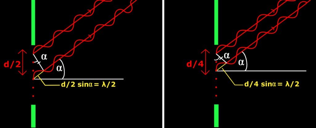
Now, waves that are not equidistant from the center — say, the waves generated by the first point and the point just below the center of the slit – on their journey to the screen, don’t travel an equal distance. One can see from the diagram that a pair of waves is out of phase when one lags the other by half the light’s wavelength. The waves then interfere destructively to produce a minimum. This would also be true for the second point and the point just below the center. One can discern a pattern – the angles at which minimums are generated.
dsin(α) = ±nλ for n = 1,2,3…
Waves that bend at an angle that satisfies this equation interfere destructively. Here, n is the integer that represents the order of the minimum. The first minimums are produced on both sides when sinα = ±λ/d. The second-order minimums are produced on both sides when sinα = ±2λ/d, and so on. Between every minimum is a maximum. Lastly, at n = 0, the central maximum is produced where one would expect a minimum. This hypothetical minimum is flanked by two maximums – this is why the width of the central maximum is twice that of the other maximums. In terms of sin(α), it is 2λ/d.
Now, look at this diagram.
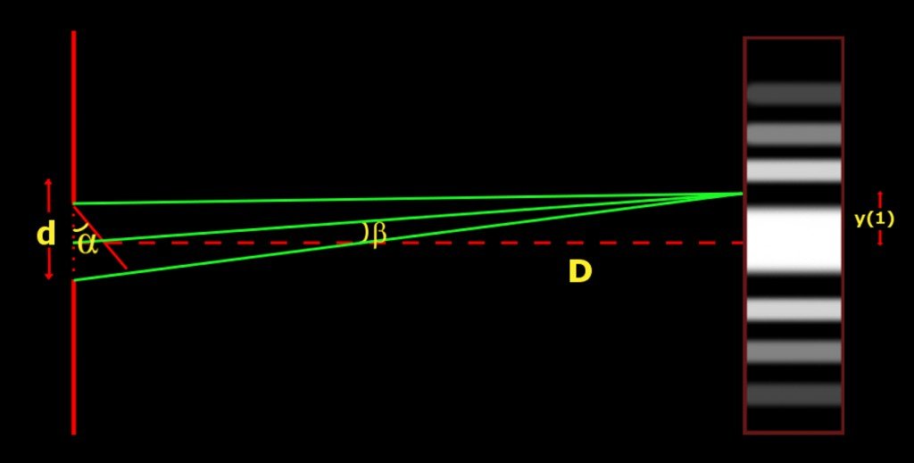
The slit and the screen are separated by a distance D, the magnitude of which is enormous compared to the slit’s meager width d. The angle drawn between two waves producing the first minimum on the screen is β. The first minimum is situated at a distance y(1) from the axis. Observe that:
tan(β) = y(1)/D
However, the angle β is so small that it is fair to write cos(β) ≈ 1, such that tan(β) ≈ sin(β). In fact, it is so small that sin(α) ≈ sin(β), such that α ≈ β.
Remember that (for the first minimum):
sin(α) = λ/d
Therefore,
y(1)/D = λ/d
Or,
y(n) = nλD/d
The implication is that if the screen distance D and the wavelength y are constant, the distance y increases or the pattern gets wider as the slit gets narrower. This is why, when the slit is narrow, the light is diffracted so spectacularly.
Now that we have discovered what determines the distance by which the fringes are separated, we can turn to the second question: Why is the central maximum the brightest, while the subordinate maximums become increasingly dimmer?
The Intensity
The intensity of a maximum in a diffraction pattern is expressed as follows:
![]()
Here, I0 is a constant with a value that is proportional to the square of the amplitude of light.
The value of sin(α) for minimums is ±nλ/d. When we substitute this in the expression, we find that the numerator is reduced to sin(nπ), which is equal to zero, precisely what we were expecting. Now, the value of sin(α) for maximums is equal to ±(n+1/2)λ/d. This is because the waves that interfere constructively travel the same distance that the waves interfering destructively do. However, they — as one can infer from the diagram — also travel an additional 0.5 λ/d. Basically, they are only approximately halfway between the minimums.
The value of α for the central maximum is 0. We calculate its intensity in the following way. As α approaches 0, so does sin {πdsin(α) /λ}. When we apply limits to the entire expression, we find that the intensity I is equal to I0. This is the maximum intensity and it is achieved when α = 0, or at the central maximum.
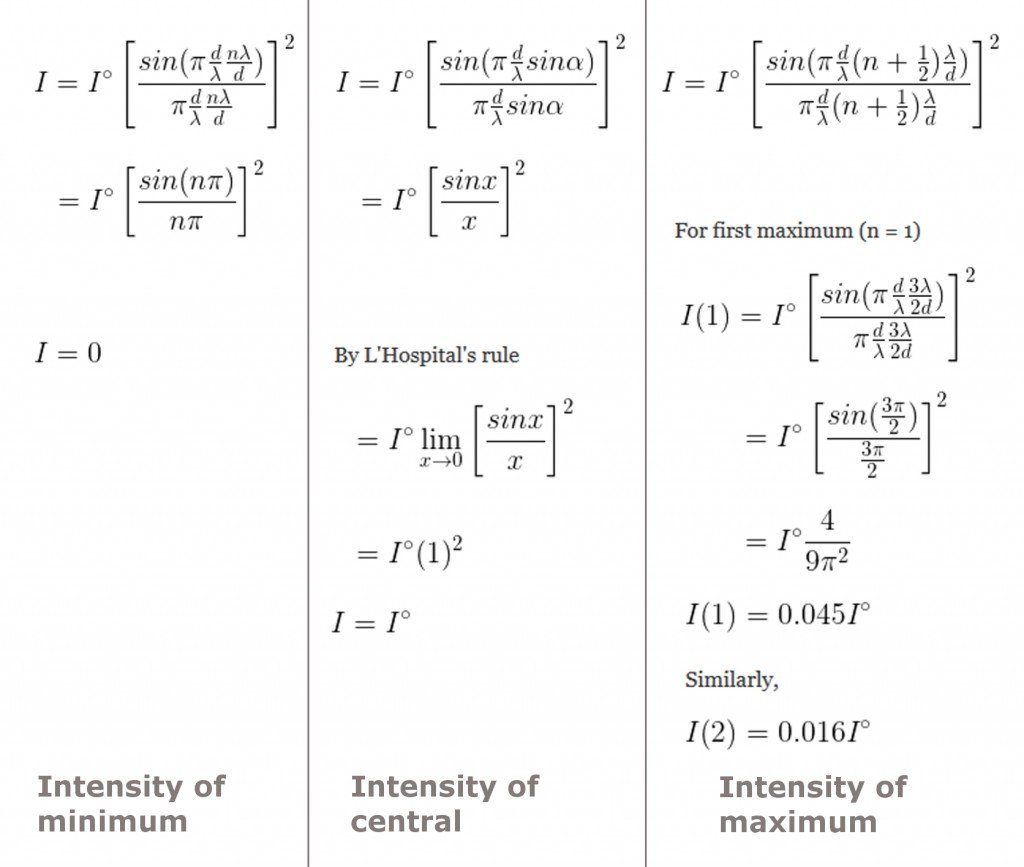
To calculate the intensity of the first or the rest of the maximums, substitute in the expression, sin(α) = (n+1/2)λ/d, where the value of n is the order of the maximum whose intensity you wish to calculate. We find that the intensity of the, say, first-order maximum, is equal to 4I0/9π2, or 0.045I0. This is a huge dip in magnitude, but it is imperceptible to the human eye.
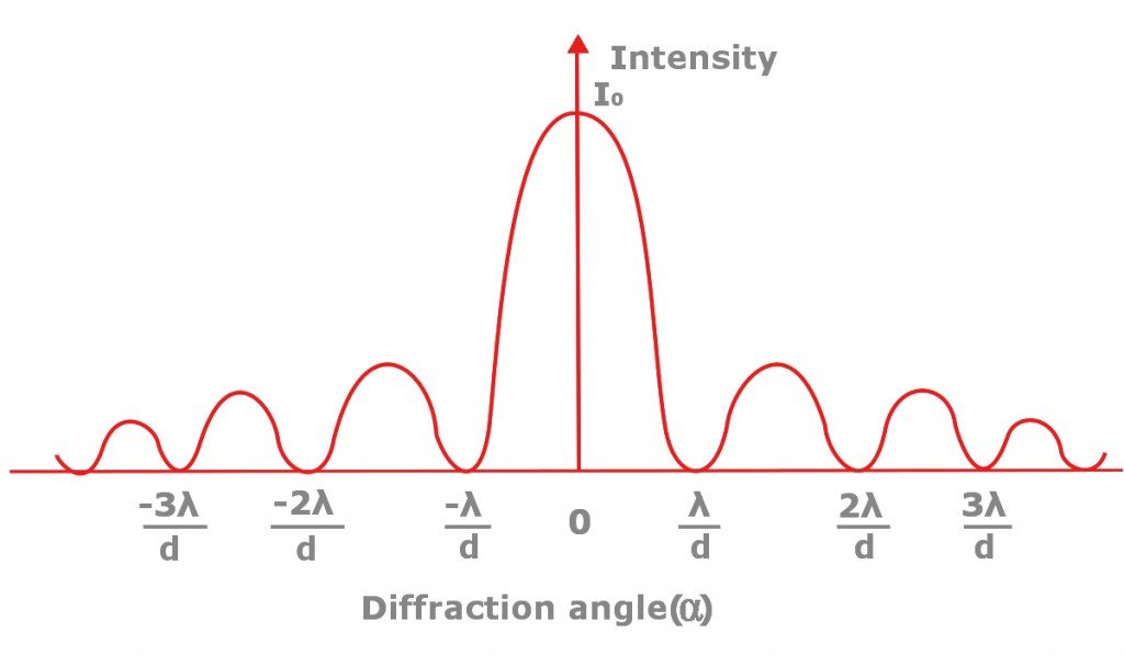
The reason why the fringes grow increasingly dimmer is that, as the order increases, so does the magnitude of the denominator. This trend ensures that the intensity declines as we move further from the central maximum. This is a graphical representation of the symmetric, dampening intensity of a typical diffraction pattern.
Also Read: What Is Interference Of Light?
What Is A Diffraction Grating?
Lastly, such a symmetric pattern is produced when the light is monochromatic and coherent. When white light — a medley of wavelengths exhibiting tremendous incoherence — is diffracted, the pattern generated is profoundly variegated. This is evident on CDs as a vague, hazy rainbow.

A CD is composed of extremely thin, equally distant parallel wires. When it is illuminated, the gaps act as slits. The width of every slit is comparable, even smaller than the wavelength of light, and therefore, every slit naturally diffracts the light. In the field of optics, such a series of extremely thin, equally distant parallel wires is called a diffraction grating.
The rules are the same: the light bends around the slit, which causes the waves to deflect as illustrated above. This renders a few in phase and others out of phase with each other. The waves then interfere constructively and destructively to produce – because they are incoherent and multi-chromatic — a variegated pattern of colors. Refer again to the expression we derived for sin(α). A diffraction grating obeys the same laws. We know that sin(α) is proportional to the wavelength λ of the diffracted light. Therefore, for slits of equal width d, red light is deflected more severely than blue light, as the former’s wavelength is much longer.
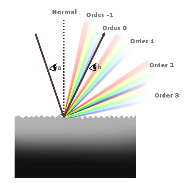
The wavelengths, from blue to red, bend increasingly. The grating therefore splits the white light just how a prism does, and what is dispersed is a splendid, iridescent rainbow on the surface of the CD.
How well do you understand the article above!

References (click to expand)
- SF Jacobs —. How a Diffraction Grating Works - University of Arizona. The University of Arizona College of Optical Sciences
- SINGLE SLIT DIFFRACTION PATTERN OF LIGHT - UBC Math. The University of British Columbia
- Experiments with Diffraction. The University of Rochester
- Single slit diffraction - labman.phys.utk.edu
- Intensity of single slit diffraction. The Santa Cruz Institute for Particle Physics