Table of Contents (click to expand)
Extension boards are multiple electrical sockets connected in parallel to each other and encased in a shockproof box. They extend the reach of electrical wall sockets by means of a flexible power cable.
To merely label extension boards as an electronic appliance is to do them a gross injustice. With one of these, you don’t have to scale walls to reach that distant power socket, nor are housemates forced to fight over who gets to charge their phone first! Multiple devices can be connected together, and this humble extension board becomes a hub of critical activity.

This nifty, plug-and-play device has an equally simple science behind it, so let’s dig in!
How Do Extension Boards Work?
A power strip or an extension board is comprised of multiple sockets connected independently to a flexible power cable and encased in a shockproof plastic shell.
It draws power from the wall sockets and distributes it amongst devices connected to these multiple sockets. Extension boards can vary in design, with some having features like individual switches and LED indicators to indicate which socket is being currently used.
The salient feature of extension boards is that they distribute power equally amongst the connected devices. This allows all devices to function flawlessly, and is achieved by connecting the individual sockets in ‘parallel’ to each other.
Ohm’s Law: How Current Flows In A Circuit?
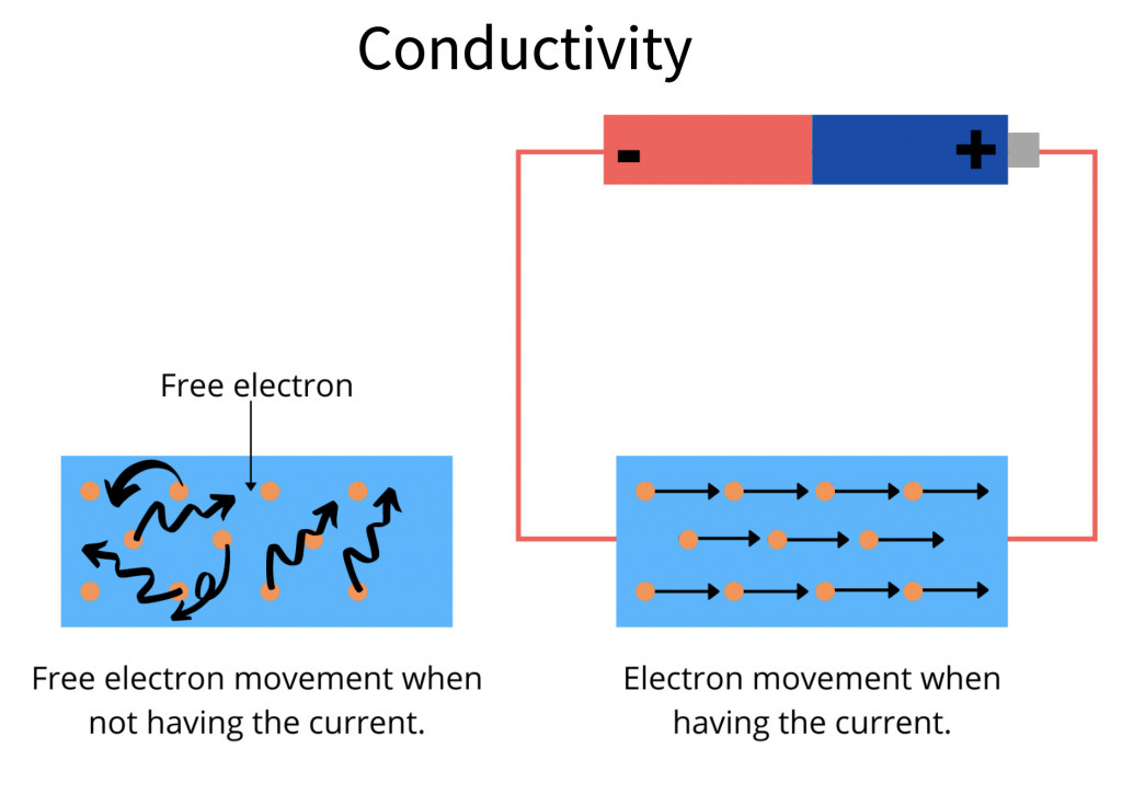
Just like water flows across two areas that have differences in altitude, current flows between two points that have differences in potential.
In order for current to flow through a circuit, it must be connected to a power supply that creates a potential difference. This potential difference is also known as voltage.
The flow of current in a circuit is governed by Ohm’s Law, which expresses voltage as a product of the circuit’s resistance and the current flowing through it.
Mathematically, it is represented as:
V = IR,
where V is the voltage across the circuit, I is the current and R is the resistance provided by the circuit to the flow of that current.
All appliances connected in a circuit consume current, thus causing resistance to it from flowing further onward in the circuit. They are therefore represented as such. Based on the arrangement of resistances in a circuit, a circuit can be classified as series or parallel.
Series Circuits
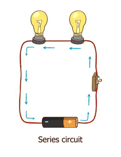
In a series circuit, all resistances (appliances) are connected in a sequence, such that the entirety of the current flows through them. In series circuits, voltage drops across each resistance, whereas the current remains constant throughout. A real-world example of a series circuit is the electric string lights used for festive decoration. One major disadvantage of a series circuit is that the failure of one appliance in the circuit leads to disruption of the entire circuit.
Parallel Circuits
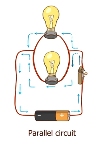
In parallel circuits, all resistances are connected to a common power source, albeit along dedicated individual paths.
As every appliance gets its ‘own’ circuit, all appliances get equal voltage. Their draw of current depends on their individual resistances, making the total current drawn a sum of the individual currents drawn by each appliance. The flow of current in one loop of a parallel circuit is not dependent on others. This makes parallel circuits useful in extension boards.
Surge Protection
While the underlying principle of extension boards is quite simple, the boards themselves are much more than a simple assemblage of parallel circuits. They must be designed keeping in mind the power consumption of appliances that will be connected to them. As parallel circuits are capable of drawing in heavy currents, it is essential to build in surge protection to prevent electrical damage or even short circuits and fires.
Power Cable Design
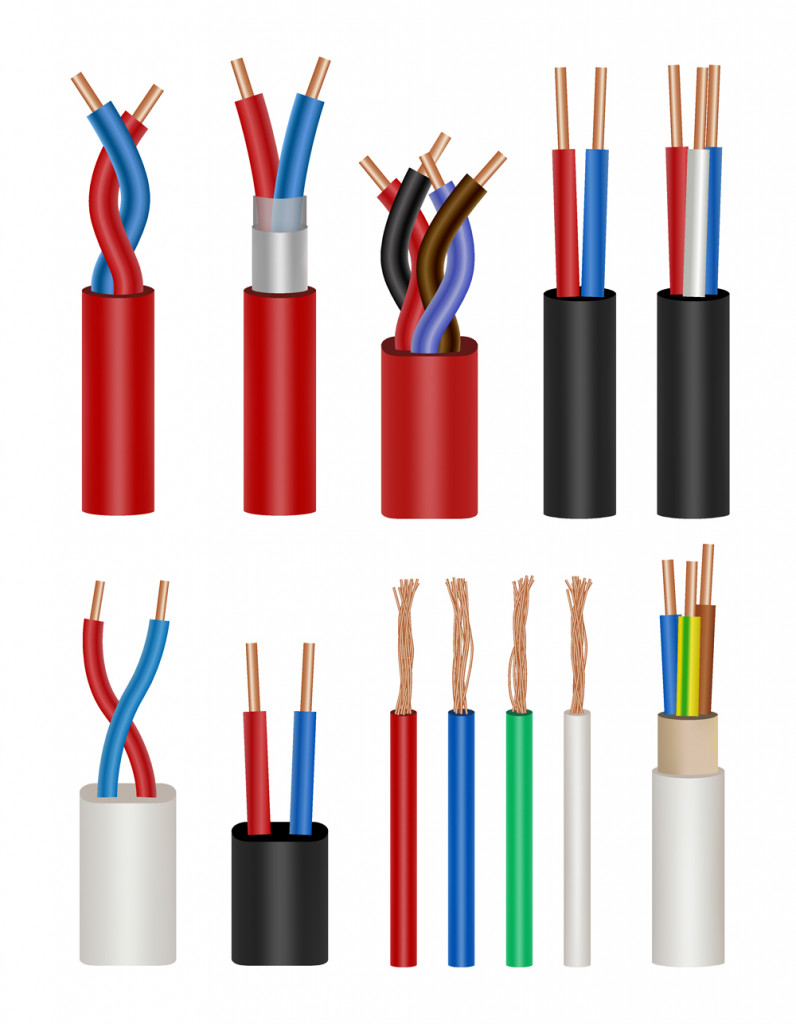
Power supply cables, generally fashioned out of excellent conductors, such as copper, are graded as per their load-carrying capacity. As a rule of thumb, thicker cables carry more current than their thinner counterparts, due to the greater surface area within the molecular structure of the cable. Similarly, the branching wires and electrical contacts that distribute current to their respective loops should be able to withstand the demand of the appliances.
When the power draw exceeds the capacity of the supply hardware, it can lead to fires and other catastrophic failures.
Fuse Cut-offs
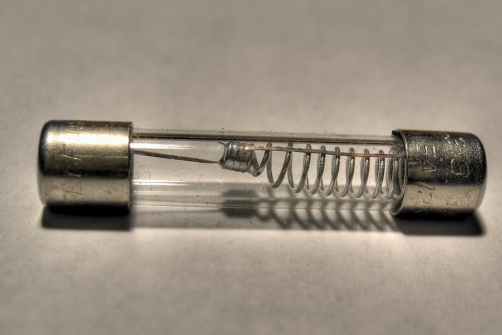
Fuses are safety devices installed between the power supply and the appliances in circuits that are capable of drawing large currents. They are made of a relatively poor conductor, such as an alloy of tin and lead. This enables them to melt when the current exceeds their rated value.
As they melt, the circuit breaks, disrupting the flow of excessive current to appliances and safeguarding them against potential harm. With the use of miniature circuit breakers (MCBs) in modern electrical mains, an additional layer of security prevails against electrical mishaps.
Grounding
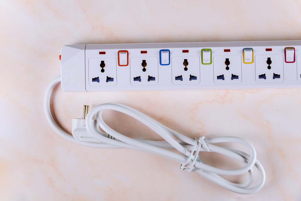
Extension boards that support multiple devices usually have a 3-pin plug to help in grounding. Earthing or grounding refers to the safe diversion of any excess current onto a surface that is consistently at low potential. This is a preventive measure for devices on board the power strip.
It is usually advised not to connect multiple heavy drawing devices to one extension board. However, if it is extremely necessary to do so, one must only use extension cords that are rated to handle such a heavy current flux. Extension boards also come with LED indicators and switches for each socket, giving users additional control. The flow of current to a certain socket can be switched on or off with their respective switch, independently of other sockets.
Also Read: What Is Electrical Earthing Or Grounding?
Advancements
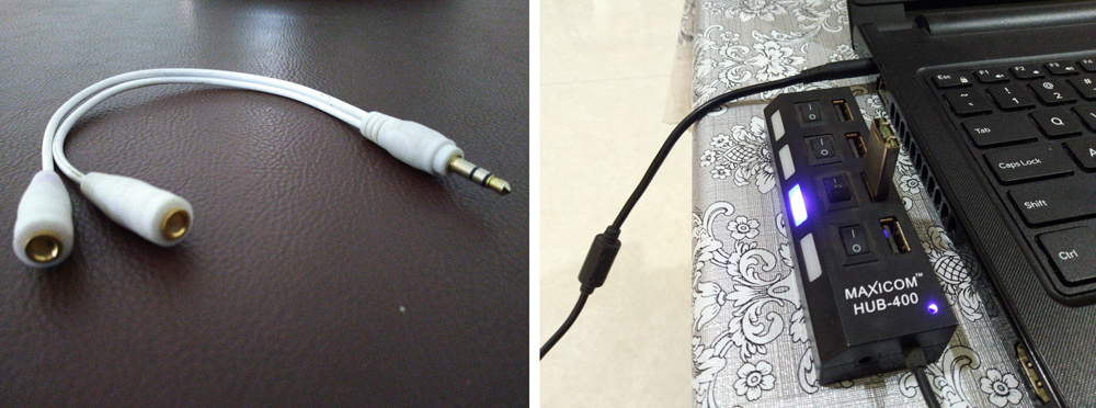
Extension boards are simple electrical tools that offer a simple, yet essential utility: Extending the reach of a power supply to suit your needs. They can be a simple cord that merely connects one appliance to the wall socket, or they can be an extended power strip that enables connecting multiple devices in one place.
Despite the paradigm shift to smart homes and wireless charging, we’re a long way from self-powering devices that work independently for extended periods without a power supply from wall sockets. However, electricity is no longer restricted to the traditional plug and socket system that only supplies electric current. Power supply options that also integrate data transfer capabilities, such as USB and HDMI, are slowly taking over traditional wall sockets, so we can expect ongoing extension technology to be developed around these advancements!
Also Read: If An Appliance Is Plugged Into The Wall, But Turned Off, Is It Using Electricity?
How well do you understand the article above!

